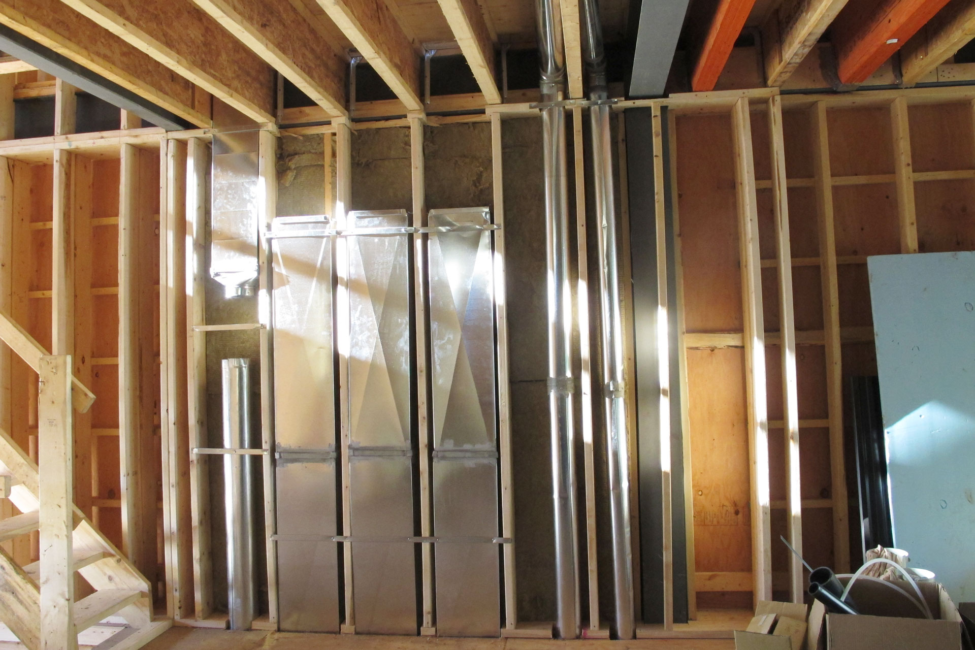
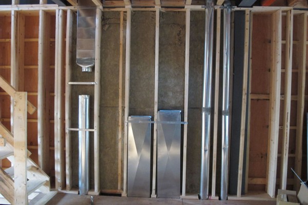
September 25th, 2014 HVAC rough in work continues. The duct wall is pretty much completed on the 1st floor. The duct won’t be fully connected because we are leaving it open until the spray foam is completed behind it.
From the left, it is 3rd floor furnace supply, 3rd floor return air, 2nd floor return air 1 & 2, HRV return air from 2nd floor bathroom, and HRV fresh air supply to the 2nd floor bedroom.

Continue reading ‘HVAC rough in day 6’ »
September 23rd, 2014 HVAC rough in work continues today.
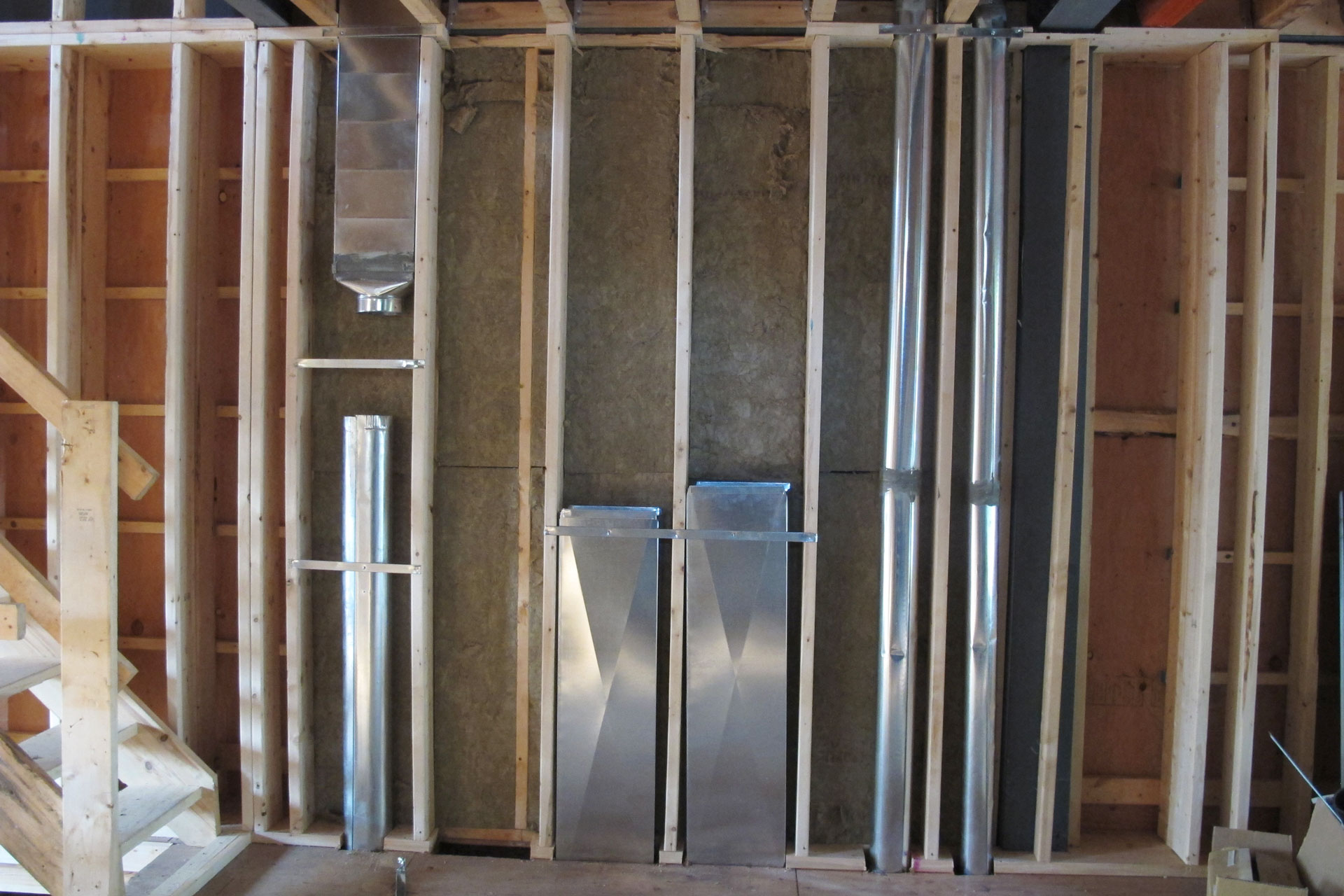
The duct wall is filling up. The left most duct is the supply duct for the 3rd floor. Then to is right the empty space will be for return air from 3rd floor. The two more square metal duct to the right are return air ducts from 2nd floor.
Continue reading ‘HVAC rough in day 5’ »
September 22nd, 2014 Dean from Hall’s Heat & Cool is back today doing more rough in work for HVAC.
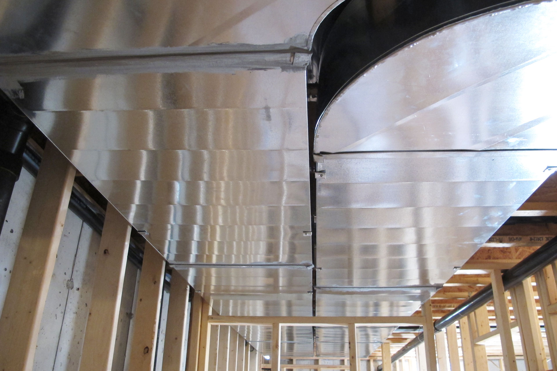
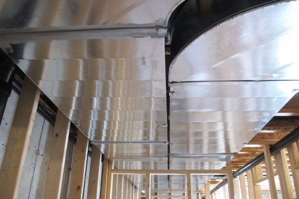
More duct works are installed. Here you can see furnace supply and return ducts are hung all the way from the laundry room to the computer server room. The supply duct is on the right and return air is on the left.
Continue reading ‘HVAC rough in day 4’ »
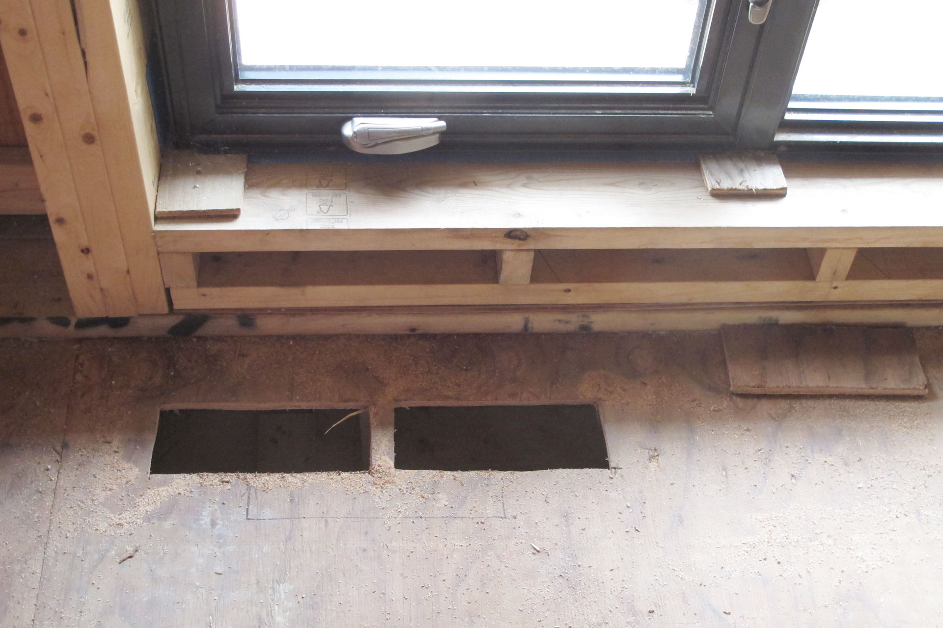
September 10th, 2014 Dean from Hall’s Heat & Cool is doing HVAC rough in together with the plumbers so that they can be sure all mechanical system fits.
A few opening they made was not at the right position. So I’ve asked them to move to the correct position.

Continue reading ‘HVAC rough in day 3’ »
September 4th, 2014 The rough-in work for HVAC continues today.
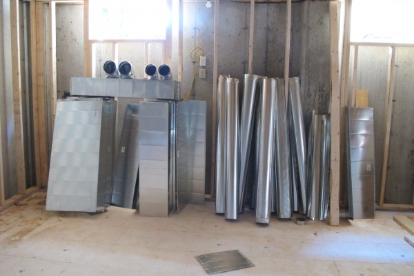
In the basement pile of ducts are now made and ready to be installed. The one that has 4 outlet on it is the very east end of the furnace supply air duct. From there two will supply my 1st floor and 2 will supply my second floor.
Continue reading ‘HVAC rough in day 2’ »
September 3rd, 2014 Dean from Hall’s Heat & Cool is here to start the rough in work for the HVAC. Dean is subcontracted by Angelo from AV Mechanical to do the HVAC for this project.
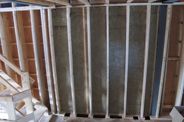
This is in the middle of the house on the north wall, a lot of cut outs is done. This is the duct wall where a lot of ducts are passing through. The wall is framed out using 2×6 stud and we have done some insulation work behind it because once covered by the duct, the area won’t be accessible to do insulation work.
Continue reading ‘HVAC rough in day 1’ »
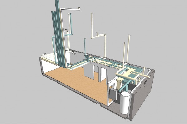
August 20th, 2014 Dean is here today to start some planning work on the HVAC duct installation. This house has a lot of duct work. There are two sets of separate duct since I want the HRV duct to run on its dedicated duct system. And the furnace is placed in the corner of the house with duct work laid out very specifically to make sure ceiling are high where it matters. And because of the small size of the house the duct must be place exactly or else it won’t have enough room to fit.
So before the HVAC work is even quotes, I have modeled all the duct work based on the revised HVAC design. I then produced a 3D layout of how I think the duct will run and give that to Dean so that he understand what I am after.
Continue reading ‘HVAC & ESA inspection’ »
April 16th, 2014 I was modeling the HVAC duct layout in 3D trying to make sure all the ducts will fit around the steel beams and inside the joists. I ran into some problem and a few changes will have to be made to the duct layout. The original design was based on an early drawing of where the steel beams will be located and was not revised after the structural steel shop drawings are finalized. It also never factored in the pluming runs that are necessary.
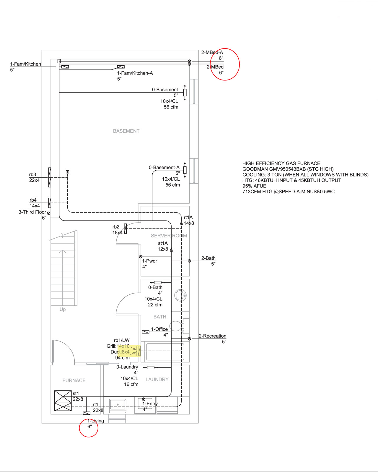
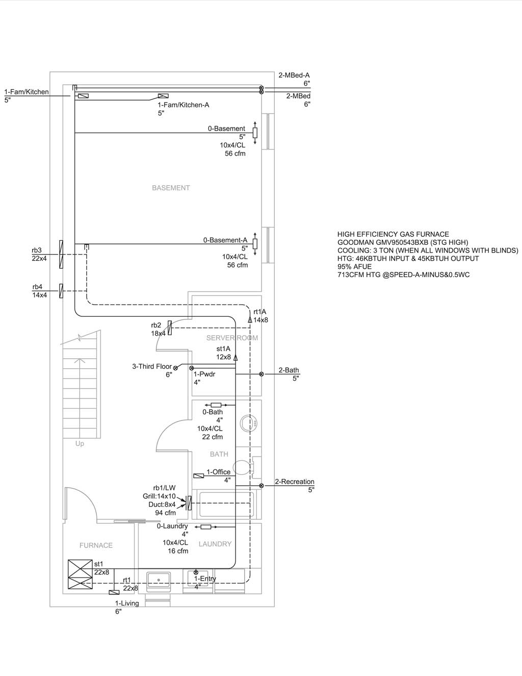
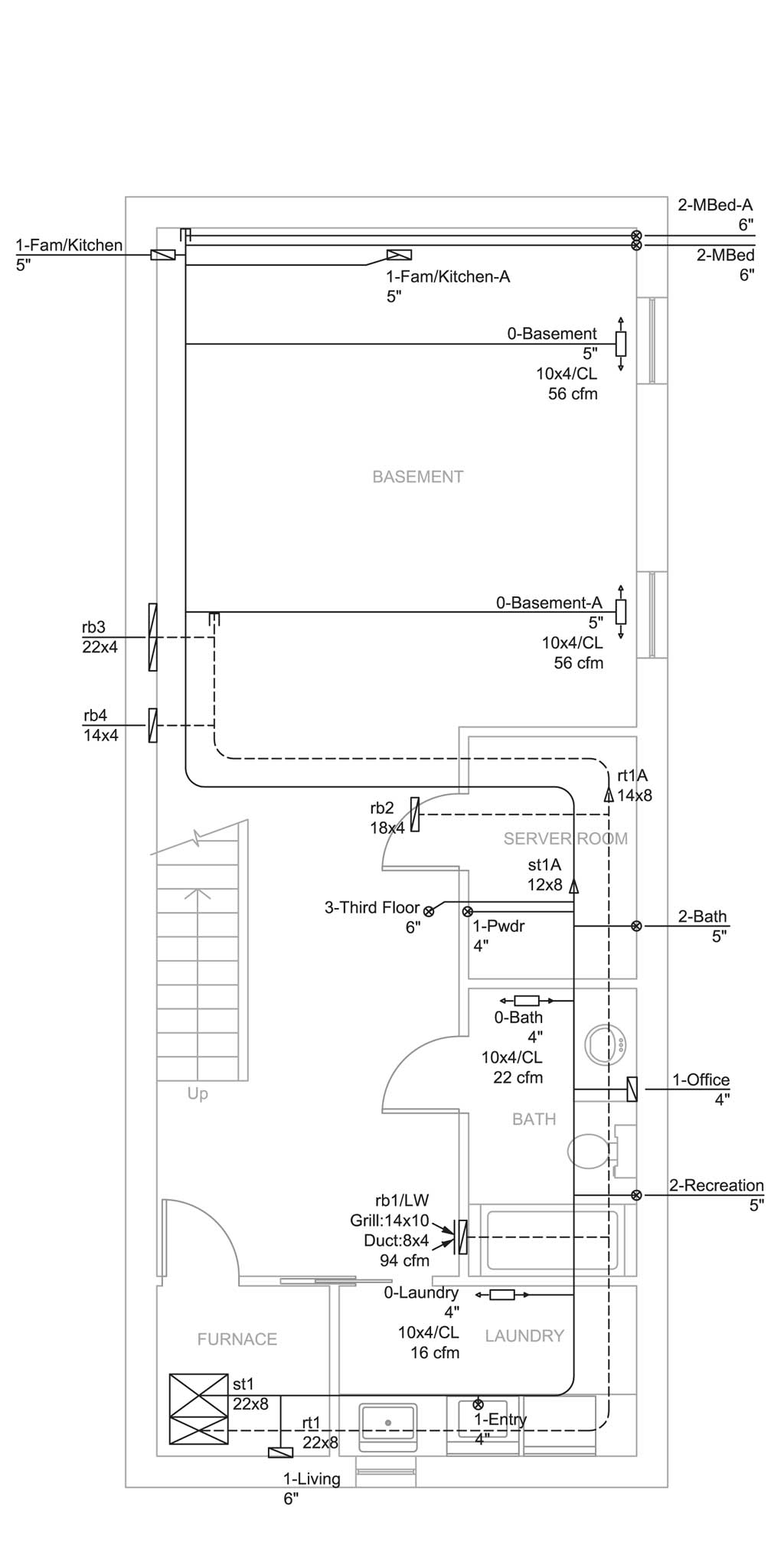
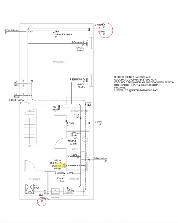
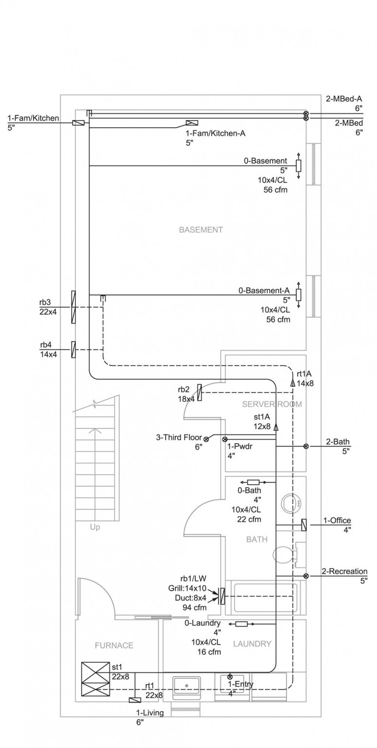
In the basement, the biggest change here is to have the supply duct 3-Third Floor duct moved to the north wall instead of in the middle house. The duct is a 6″ duct and will not fit inside interior walls. And the original planned route for that duct has tons of obstacles due to structural steel in the upper floors. So go all the way up the north wall is the best solutions to conceal all the duct works inside the ceiling. The supply duct 0-Basement-A changed also have to be changes so that it comes in from the computer server room instead of from the north wall. Otherwise the duct will have to run below the joist because there’s a steel beam that runs vertical where it would have crossed the house.
Continue reading ‘HVAC design revised’ »
July 29th, 2013 One of the things we were missing for building permit application last Wednesday was signed Schedule 1 Designer Information from the HVAC designer and signature on the drawing and the heat loss calculation. We informed Haibo Chen from Fulford Supply that we needed the form from him and I’ve also sent him a few minor revisions. Mr Chen came through on Monday with the files. We’ve also got signed drawings from Ben Mashhadi of ABM Engineering. So finally I think we have everything we need to get the building permit application through.
Here’s the final HVAC duct layout. Not a lot has been changed, just some minor relocation. We’ve done most of the work on the structural engineering on the placement of the steel beams to make the duct layout work.
Basement duct layout:

Continue reading ‘HVAC design final’ »
April 20th, 2013 My house design calls for a ductless heat pump that will provide the main cooling and heating with a backup heating via standard forced air furnace. The reason for the need for a backup heating source is that most air-to-air heat pump will stop working by -15°C. Now in Toronto, there are not many days (nor that many hours during the day) in the winter where temperature will fall below -15°C. However, a backup heating source is still necessary to ensure that we are not in the cold when the heat pump had to be turned off. I’ve also called for separate ducts for a Heat Recover Ventilation because that’s the right way to bring fresh air into a relative air tight house.
For the HVAC design we have contracted Haibo Chen from Fulford Supply. Mr Chen told me that in Toronto the design temperature is -20°C. Because the air-to-air heat pump will no longer be working at -15°C, so even though I consider the furnace as the back source, during the design stage for building permit, it is probably better to just have the furnace as the main source of heat. Then once I have all the heat loss information, I can simply choose the heat pump to match the heat loss numbers. The total charge is $750 for the furnace duct design and heat loss calculation, and $200 for HRV calculation and design. Mr Chen is very prompt with the work. We started the work on April 11 and he provided his preliminary drawings on April 19, one week after the work started.
Here’s the furnace duct design.
Basement:
Continue reading ‘HVAC design’ »
|
|