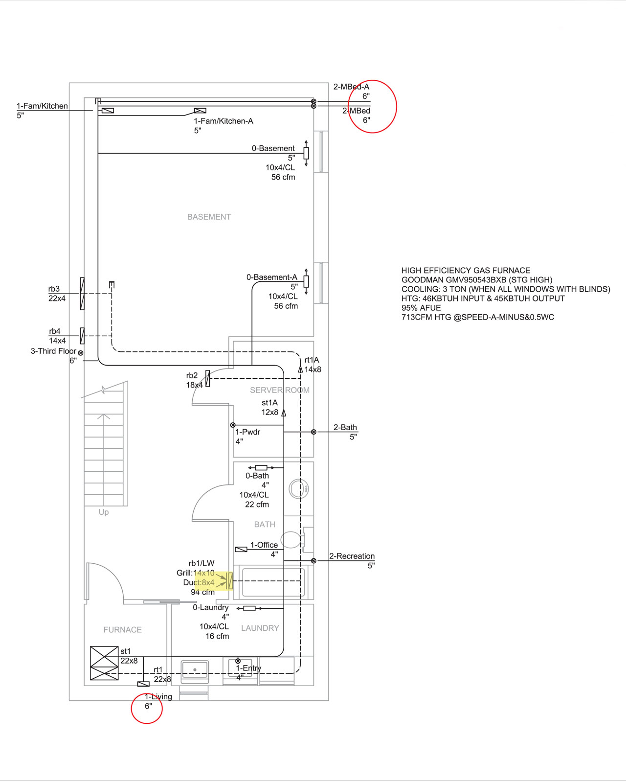
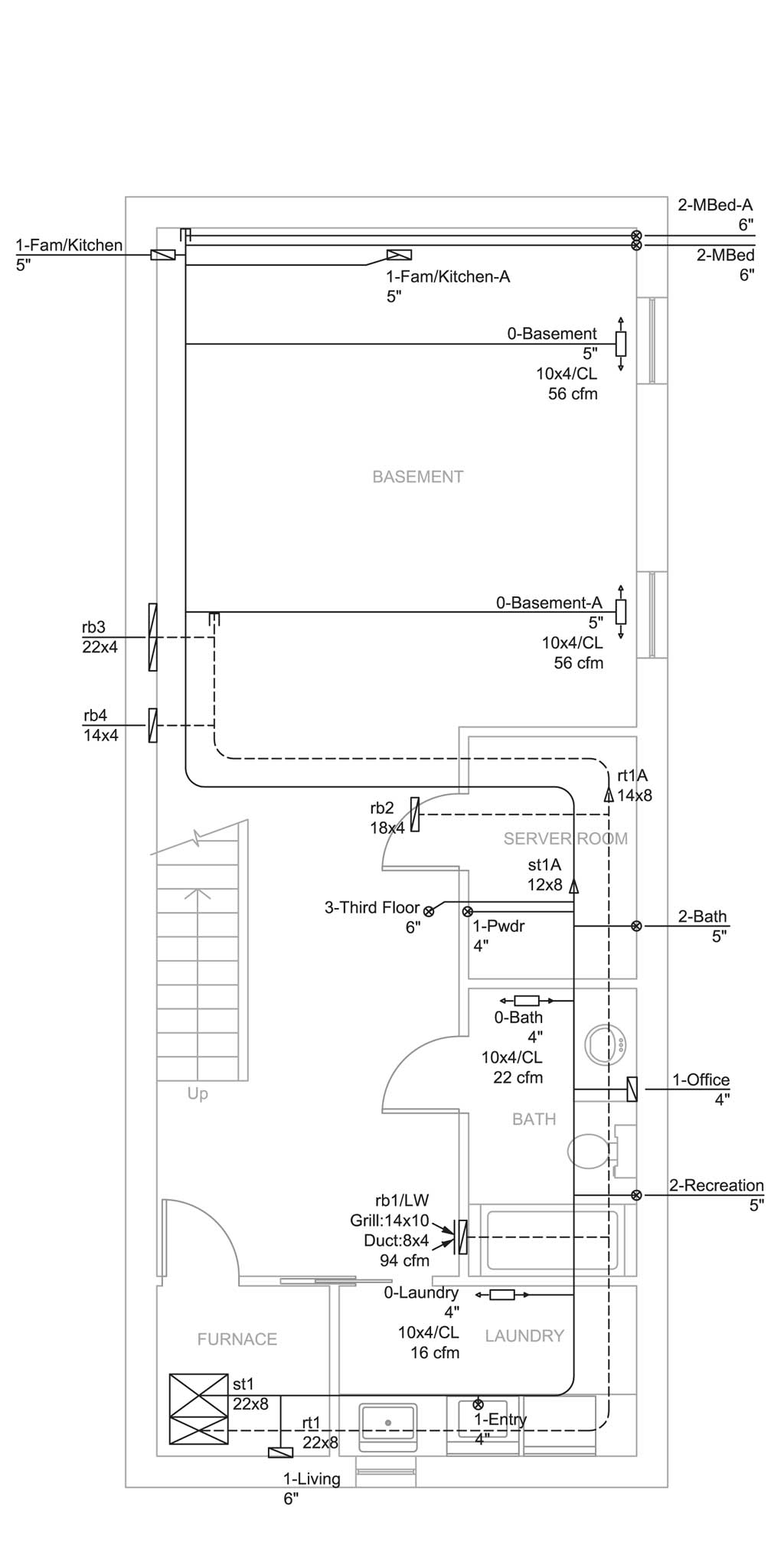
April 16th, 2014 I was modeling the HVAC duct layout in 3D trying to make sure all the ducts will fit around the steel beams and inside the joists. I ran into some problem and a few changes will have to be made to the duct layout. The original design was based on an early drawing of where the steel beams will be located and was not revised after the structural steel shop drawings are finalized. It also never factored in the pluming runs that are necessary.
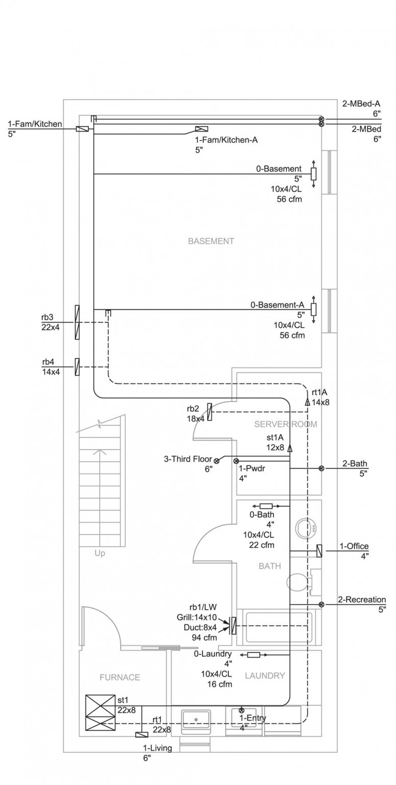
In the basement, the biggest change here is to have the supply duct 3-Third Floor duct moved to the north wall instead of in the middle house. The duct is a 6″ duct and will not fit inside interior walls. And the original planned route for that duct has tons of obstacles due to structural steel in the upper floors. So go all the way up the north wall is the best solutions to conceal all the duct works inside the ceiling. The supply duct 0-Basement-A changed also have to be changes so that it comes in from the computer server room instead of from the north wall. Otherwise the duct will have to run below the joist because there’s a steel beam that runs vertical where it would have crossed the house.
Continue reading ‘HVAC design revised’ »
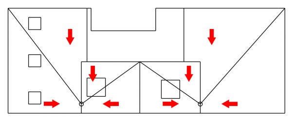
March 30th, 2014 The design of the big marshmallow house calls for a flat roof to build a roof top terrace. Flat roof, it is actually not technically correct. You will never build a house with a real flat roof. Because if you do, you will have problem with water sitting on top of the roof causing damage to the house. The accurate term will be a low slope roof. The “flat roof” still have a slope to facilitate water drainage, just at a very low angle. Any roof that has slope of less than 2:12 or a rise of 2″ over 12″ or 9.5 degrees is considered to be a low slope roof. I have designed my low slope roof with two interior roof drains. But to have proper drainage, the roof needs to be slopes so that the water flows towards the roof drains.
And this is what the framer came up with. Below is a top view of the house with the north pointing up. The two circle on the bottom (south side) is where the two roof drains will be located. The four diagonal lines are valleys while the vertical line in the middle is a peak. The north side is about 4″ higher than where the roof drain is. Making this roof with an overall slope of 4″ rise over 15′-8″ or 1.2 degrees. And as you can see with those diagonal valleys and the peak in the middle, the design manages to push all the water towards where the roof drains will be as indicated with the red arrows.
Continue reading ‘Roof drainage’ »
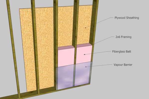
March 9th, 2014 Because of the structural steel, our exterior wall needs to be at least 8.5″ thick to hide all the steel beams. I have done some research on wall constructions to see how to construct that 8.5″ thick wall that will provide the best performance. And we ended up with a design with deep Swedish roots. In this post, I will try to explain why we framed the wall the way we did.
The illustration below is what a traditional stud-framed wall looks like. To satisfy minimum code with the use of fiberglass insulation, the walls are constructed as a 2×6 stud-framed wall. Plywood or more commonly seen now OSB (Oriented strand board) wall sheathing on the outside. The stud cavity is typically filled with figerglass batts which offers about R20. Then 6 mil polyethylene vapour barrier is added to the inside and gypsum drywall to finish up the interior. That’s how a typical wall is constructed today.
Continue reading ‘Exterior wall construction with Swedish roots’ »
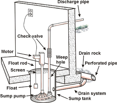
December 5th, 2013 Today I was talking to the city inspector and he informed me that I am not allowed to have weeping tiles tied into the sewer. He indicated that weeping tile must be routed to an interior sump pit and a sump pump will pump the water out above grade. Now that’s yet another blow to my building project both for planning and for cost. Planning wise, I’ve already back filled most part of the house. Now excavator will have to come and dig up the north west corner again so that they can add a T joint on the weeper and then put a pipe under the footing into the house. Cost wise, I don’t know how much extra it will cost me to dig the hole again, but the sump pit and the pump and the extra plumbing will cost me around the neighbourhood of $1500.
Continue reading ‘More plumbing issue’ »
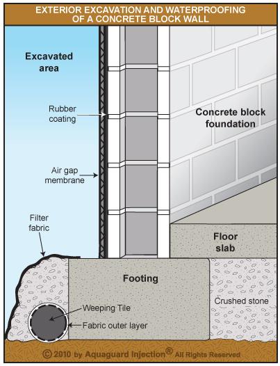
November 29th, 2013 In my previous post Foundation wall water proof, you can see that the weeping tile is installed. The weeping tile which is a 4″ perforated pipe has white fabric sock around it to prevent sediment from entering the weeping tile. Then the weeping is buried in a pile of 3/4″ clear gravel. Gravel also filters sand and sediments from water and it provides a good drainage backup to the weeping tiles in case the weeping tile system is clogged. Now to maintain that good drainage property of the gravel, it is a best practice to lay a layer of filter fabric around the gravel so that sediments doesn’t enter the gravel layer and therefore maintain that good drainage of the gravel layer.In fact the ideal installation would be lay the filter fabric down first, and put a thin layer of gravel down. Then put the weeping tile and pile a thick layer of gravel on top. And finally wrap the filter fabric around the gravel before back fill.
Continue reading ‘Improving the weeping tile installation’ »
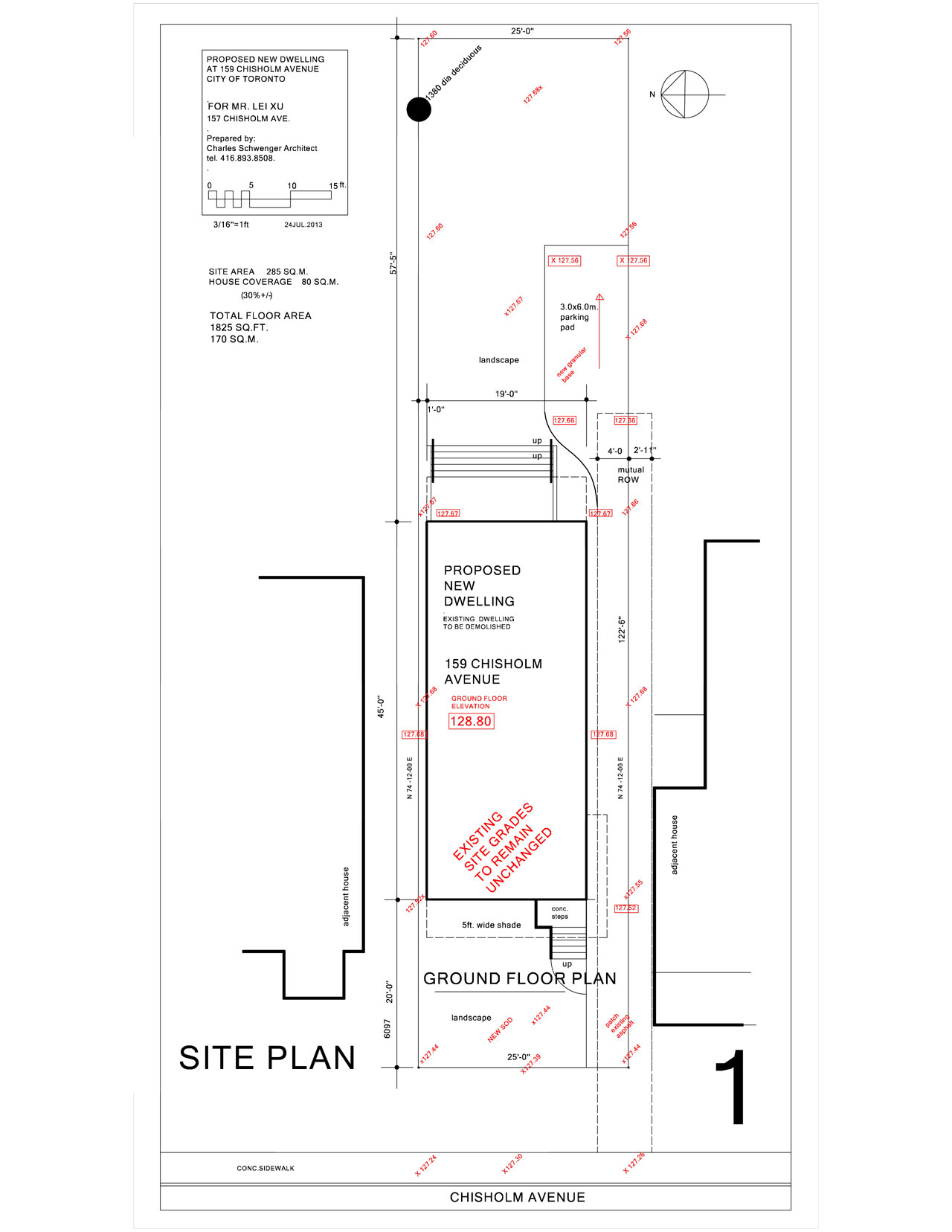
July 31st, 2013 Today is the last day of July. I have finally gathered all the files with proper signature on them. So here we go again to the city’s building department to submit the application for building permit. This time everything went smoothly. The computers are working, and we didn’t miss any critical files. We still missed an Energy Efficiency Design Summary, but we can submit that later. So after about an hour and half, the building permit application is submitted. The cost of the building permit application is just shy of $3000.
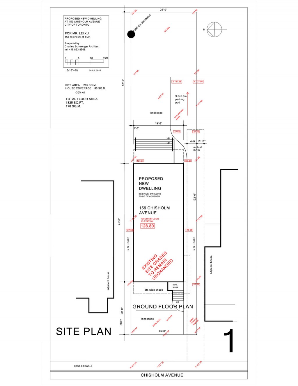
And so here is The Big Marshmallow House design as submitted for permit.
Site plan:
Continue reading ‘Building permit application submitted’ »
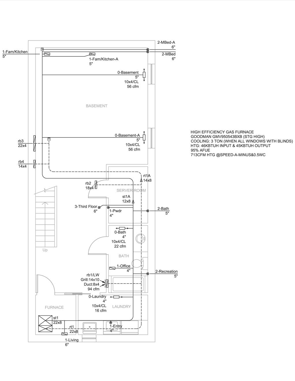
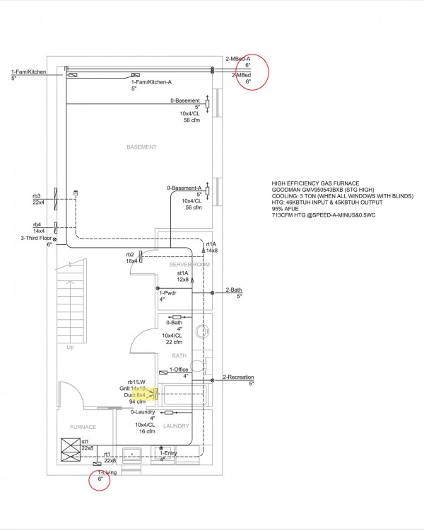
July 29th, 2013 One of the things we were missing for building permit application last Wednesday was signed Schedule 1 Designer Information from the HVAC designer and signature on the drawing and the heat loss calculation. We informed Haibo Chen from Fulford Supply that we needed the form from him and I’ve also sent him a few minor revisions. Mr Chen came through on Monday with the files. We’ve also got signed drawings from Ben Mashhadi of ABM Engineering. So finally I think we have everything we need to get the building permit application through.
Here’s the final HVAC duct layout. Not a lot has been changed, just some minor relocation. We’ve done most of the work on the structural engineering on the placement of the steel beams to make the duct layout work.
Basement duct layout:

Continue reading ‘HVAC design final’ »
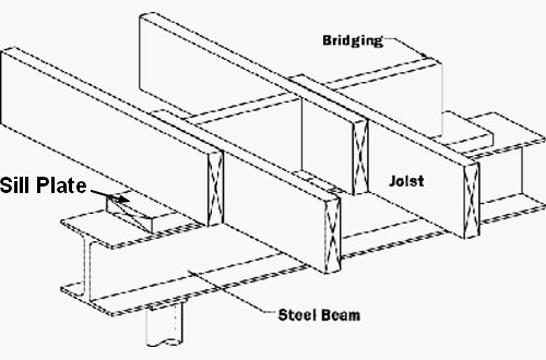
July 23rd, 2013 We are now approaching the last week of July. Finally after a few rounds of back and forth between the joist designer and the structural engineer, we finally come to an acceptable design for the joist layout. There is a few things that’s very specific for this house. First of all, because of the heat pump outlet, there are a few 2′ x 2′ cutouts in the ceiling of the first and second floor to accommodate the heat pump outlet. Then there’s the sky lights on the roof, I have two 3′ x 3′ skylights and three 2′ x 2′ skylight scattered around the roof. And finally there’s the problem of how to secure the engineered I-joist to my steel beams. For a wood framed house, hanging engineered I-joists is simple, just nail your typical joist hanger to the headers and slide the I-joists onto the hangers. However, my house has a steel frame, so it requires a different approach.
There are a few ways to hang joists with steel beams. One method that a lot of us are familiar with is the way typical house today uses for the ground floor on top of a steel beam in the basement. What you do is you put a sill plate on top of the steel beam. Then you would just place joist right on top of the steel beam and put blocking in between to prevent lateral movement. Something that looks like this:
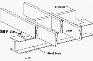 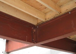
I cannot place the joist on top of the beam. I have steel beams that runs right across the house, which mean if I place the joist on top of the beam, I will end up having the beam right in the middle of the house. My design calls for a flat ceiling.
Continue reading ‘The different ways to hang I-joist’ »
May 22nd, 2013 Today preliminary drawing from structural engineering came back. Ben has designed a complete steel frame on special concrete piers. There are some design issues but the additional cost for the steel frame worries me the most. I like the idea that I would probably have the only house that’s steel frame structured around here. I also like the idea that this steel structure is very well engineered to take whatever that’s thrown at it. But I am certainly not willing to break the bank for it.
Here’s the initial version of the structural drawing.
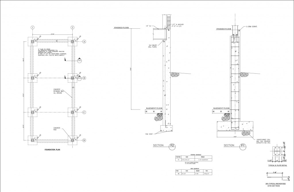
Continue reading ‘Preliminary drawing from structural engineering’ »
April 20th, 2013 My house design calls for a ductless heat pump that will provide the main cooling and heating with a backup heating via standard forced air furnace. The reason for the need for a backup heating source is that most air-to-air heat pump will stop working by -15°C. Now in Toronto, there are not many days (nor that many hours during the day) in the winter where temperature will fall below -15°C. However, a backup heating source is still necessary to ensure that we are not in the cold when the heat pump had to be turned off. I’ve also called for separate ducts for a Heat Recover Ventilation because that’s the right way to bring fresh air into a relative air tight house.
For the HVAC design we have contracted Haibo Chen from Fulford Supply. Mr Chen told me that in Toronto the design temperature is -20°C. Because the air-to-air heat pump will no longer be working at -15°C, so even though I consider the furnace as the back source, during the design stage for building permit, it is probably better to just have the furnace as the main source of heat. Then once I have all the heat loss information, I can simply choose the heat pump to match the heat loss numbers. The total charge is $750 for the furnace duct design and heat loss calculation, and $200 for HRV calculation and design. Mr Chen is very prompt with the work. We started the work on April 11 and he provided his preliminary drawings on April 19, one week after the work started.
Here’s the furnace duct design.
Basement:
Continue reading ‘HVAC design’ »
|
|